Arduino: Basic programming concepts
New to Arduino? This is a great place to start learning and get into some of the more advanced programming topics.
Our code samples are there as images – you have to type them in. You can’t copy and paste. We do it this way because it’s an important part of the learning process.
Sometimes, we stand on the shoulders of others. We refer you to some other web pages and youtube videos to explain some of the concepts. They may not follow the same structure as our class, but they do explain the concepts very well.
First lesson: we get into the basics of coding on Arduino and what we think are some best practices.
Second lesson (starting at section 3.4): we get into our first hardware additions, and controlling them with interrupts
Third lesson (starting at section 4): we go through the basics of handling interrupt timers. Then in section 5, we give you some pointers for using libraries using a popular Arduino range sensor.
1.1 Arduino programming: the basic function structure
If you already know how to program, you can breeze through this section pretty quickly and get to 1.2
The most common Arduino programming language is a slightly modified version of C.
In C, everything is based on functions that look like this very simple example for computing the square of a number
int square(x) {
int mysquare = x * x;
return (mysquare);
}
We would call this function with something like this:
y = square(2)
2 becomes the x in the function definition, and y will get back the value of 4.
Let’s break down each line of that simple function.
int square(x) {
- int in front of the function name tells us what kind of result the function will return. In this case, int is an integer.
- If we are not returning anything (yes, that’s OK): we give the function a type of void
- square is the name of the function
- (x) is the parameter being passed to the function
- We could pass multiple parameters, separate by commas. Example: (x,y,z)
- We could pass no parameters. Example: ()
- { (we call it “squiggly bracket) is the start of the function definition, which is everything between the first { and it’s corresponding }
int mysquare = x*x;
This is a command inside the function
We are creating a new variable here called mysquare. In C, we need to tell the program what kind of data mysquare represents. It’s an integer, so we precede it with int.
mysquare is the square of the x value passed to the function.
Every command line in a function ends a semicolon. If you forget the semicolon on any line, it won’t work.
return(mysquare);
return is how we give back the result of our function.
If we are not returning anything, we can leave out that line.
Don’t forget the semicolon!
}
That’s the squiggly bracket that ends the function
Variable and function names: CASE IS CRITICAL
In the C language, case is critical for variable names and function names. So MySquare is seen as something completely different from mysquare. And square is completely different from Square.
1.2 The basic Arduino program structure.
Every Arduino program contains two standard functions:
void setup() {
// some commands
}
void loop(){
// some more commands
}
// indicates a comment, It’s the only line that doesn’t require a semicolon at the end.
The setup() function runs once before anything else. It’s used to do some basic setup on the board
The loop() function is the main function of the program. It runs forever. When it gets to the last line of the function, it goes back to the first line and repeats.
Did you notice that:
- Both functions are of type void. They never return anything.
- Because they are both void, they don’t need a return() statement.
2. Our first Arduino program
Everybody’s first Arduino program consists of blinking an LED on the Arduino board.
It’s so common that we won’t bother telling you how to do it – just check out Paul McWhorter’s excellent video on how to start the Arduino IDE and run your first program.
The program will look like this:
void setup() {
pinMode(13, OUTPUT);
}void loop() {
digitalWrite(13, HIGH);
delay(1000);
digitalWrite(13, LOW);
delay(1000);
}
Follow Paul’s video, and type the program. DON’T CUT AND PASTE IT! Accurately entering the program will all the correct patentheses, squiggly brackets, semicolons and case for each variable and function name is critical. YOU NEED THE PRACTICE.
2.1 Our first modification – using a constant name instead of a number.
13 in the first program is the pin number that has the LED connected to it on an Arduino Uno.
Problem is, different types of Arduino board can have the built-in LED on different pins.
To make it easier on ourselves, we can define a CONSTANT using a define statement, then use the constant name in our program, This way, if we are using a different type of Arduino board, we only have to change the value in one place.
Modify your program to look like this:
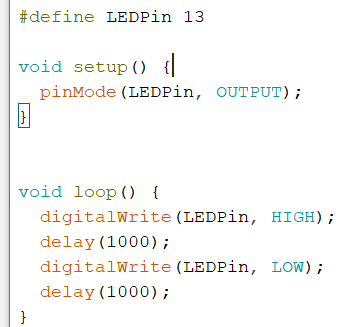
Now if we have a different board type, we only have to change the pin number in the #define statement
You might have noticed by now that the program above is an image. You can’t cut and paste the code into the IDE. As we said earlier, it’s critical for learning and getting accustomed to the C code that you type the code in yourself.
2.2 An even better improvement – board-specific default define statement
The Arduino IDE knows what type of Arduino board you have.
If it knows that, then it might also know what pin has the built-in LED. And it does.
The constant LED_BUILTIN will automatically provide the correct pin number.
OUTPUT, HIGH and LOW in the code above are also pre-defined constants. You can read about pre-defined constants here.
So now you can remove the #define statement and change your code to look like this:
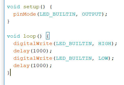
Our code is more compact and will work on any Arduino board with a built-in LED – no matter what the pin number.
2.3 Blinking the LED with different intensity
Arduino doesn’t have variable power outputs on its pins. It’s either 0 volts or 5 volts.
To simulate variable outputs, we can quickly power the LED off and on. You won’t see it going off – it’s so fast, it will just appear more or less bright, depending at what rate you cycle the power.
Cycling the power in this way to create an average power level is called Pulse Width Modulation (PWM).
Paul McWhorter explains PWM in this video.
To demonstrate PWM, enter this program
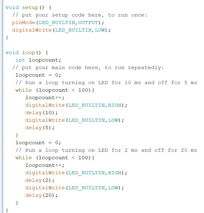
You will see the LED brink alternately between low and high intensity.
Using a programming loop to run the PWM is a lousy way of doing it. People call it “big banging”.
Why is bit banging bad? Because the microcontroller on the Arduino can do it for us automatically!
3. The World’s Simplest Oscilloscope – with PWM visualisation
3.1 The basic oscilloscope – PWM levels
We took this idea from Oyvind’s Arduino Oscilloscope with 7 lines of code – and improved it. You can try starting with this example, or jumping to our improved one below.
In this code, we’re going to do several things:
- Set up a serial port output. This will allow us to send the measurements back to our computers over the USB cable
- Learn to use the Arduino IDE’s serial port monitor. It can display the numbers for us, or plot them for us.
- Set up analog and digital outputs on the Arduino pins.
- Read analog inputs from the Arduino pins
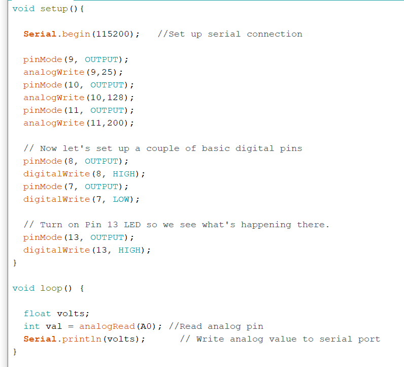
analogWrite is how we write PWM outputs on Arduino pin without having to do a program loop.
analogWrite supports 255 levels, with 0 being off all the time, and 255 being on all the time.
In between:
- 128 averages on and off half of the time (it’s about half of 255) – so average of 2.5 volts
- 25 averages on and off about 10% of the time (it’s about 10% of 255) – so average of 0.5 volts
digitalWrite is how we write 0 or 1 – or in this case, LOW or HIGH, or 0V or 5V for a binary value.
So we are setting up:
- pins 9, 10 and 11 for analog levels of 25/255, 128/255, and 200/255 PWM
- pin 7 for digital 0 (LOW) and pin 8 for digital 1 (HIGH)
Finally we set up pin A0 to read the values. We are setting up A0 as analog input with the analogRead() function. How does it work?
- It expects inputs between 0 and 5 volts
- It reads it as a 10 bit value – that means 2-to-the-power-of-10, which is 1024. So the 0 to 5 volt range is divided into 1024 values ranging from 0 to 1023. A reading of 2.5 volts will give a value of 511.
Here’s the code:
One the code is running, do this:
- From the IDE Tools menu, run Tools -> Serial Monitor
- Make sure the speed is set the same as our code: 115200.
- Plug one end of the wire into A0, Leave the other end dangling.
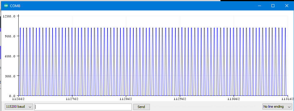
Values are flying by on the screen. What do you think is happening?
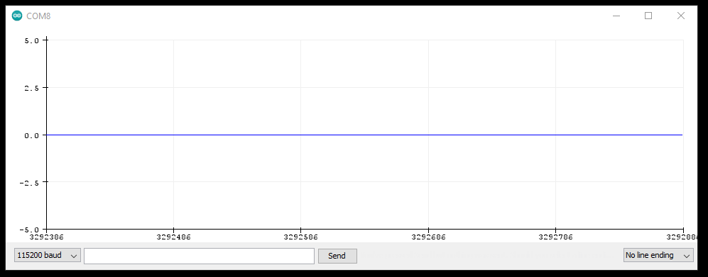
To get a better perspective, close the Serial Monitor and open Tools -> Serial Plotter
There is enough electromagnetic radiation coming from lights, wiring and everything else in the room to generate a small current in the pin. It’s really small… and the Arduino is sensitive enough to measure it!
Note: if the plotter is not showing anything:
- Check the speed. See the bottom left corner of the image above? That value of 115200 has to match the value in the Serial.begin() function of our code
- Close and re-open the plotter. That’s sometimes required after reloading the Arduino board
Next step:
Use the wire that’s plugged into A0 on the board and, one after another, plug the other end of the wire into the pins we set up as output in our code (7,8,9,10,11).
Do you see how the different PWM settings cycle the power on and off?
Do you see the digital LOW and HIGH ?
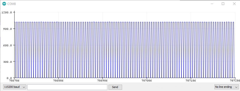
You should have seen the following:
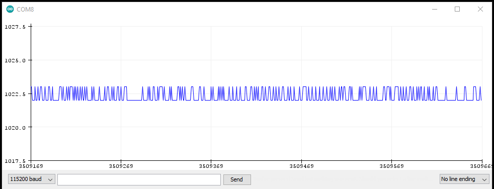
We expect the digital HIGH to be around 5 volts. If you don’t understand why it’s reading steadily around 1023, re-read the paragraphs above about analog input.
Additional exercise: try increase the speed in Serial.begin() and the serial plotter to the maximum value of 2000000. Does this improve and increase the quality of the plot? Try it again, dropping the speed to the minimum value of 9600.
3.2 Improving the oscilloscope: displaying voltage instead of PWM
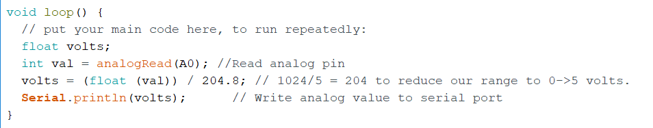
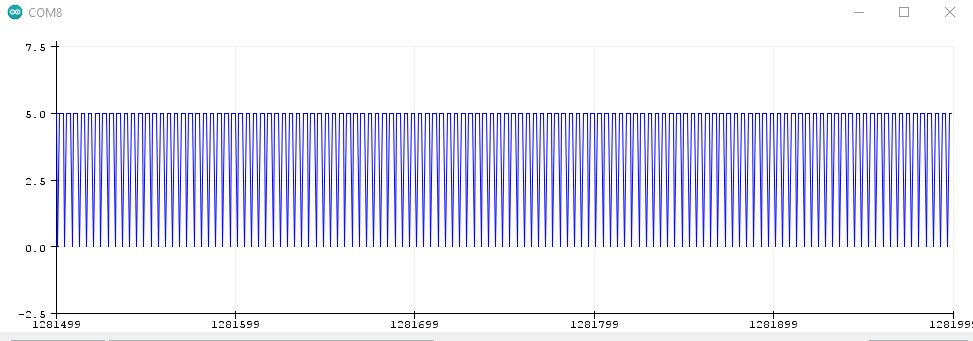
Oscilloscopes read volts. If we want our plot to read in volts, all we need to do is add one line of code to our program.
If 1023 is 5 volts, we can divide it by 204.8 so that it the serial plotter reads 5 instead of 1023.
Problem: that A0 analog input value is an integer (whole) number. If we are reducing it to a 0-to-5 range, we need to handle decimal points or we’ll have the values jumping between the numbers 0, 1, 2, 3, 4 and 5 with nothing in between. That’s why, in the plot for Pin 8 above, the plot jumps between 1022 and 1023.
Change our void() loop in the preceding program to look like this:
- We declare a new variable called volts as floating point so it can have values after the decimal point
- In the calculation, we have to convert val to float. The C language is very particular about things like that
Each time you change the program, you may need to stop and restart the Serial Plotter
Connect your wire from A0 to each of the outputs (7,8,9,10,11) to get an actual voltage reading and see how your plots have changed.
3.3 Push it more: A three channel scope!
Let’s push our little board even more – can we plot all three of our PWM outputs at the same time?
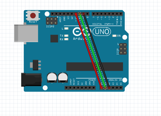
The wiring
- Unplug your Arduino from your computer. It’s always a good idea to do this when wiring
- Plug a wire from pin A0 to pin 11
- Plug a wire from pin A1 to pin 10
- Plug a wire from pin A2 to pin 9
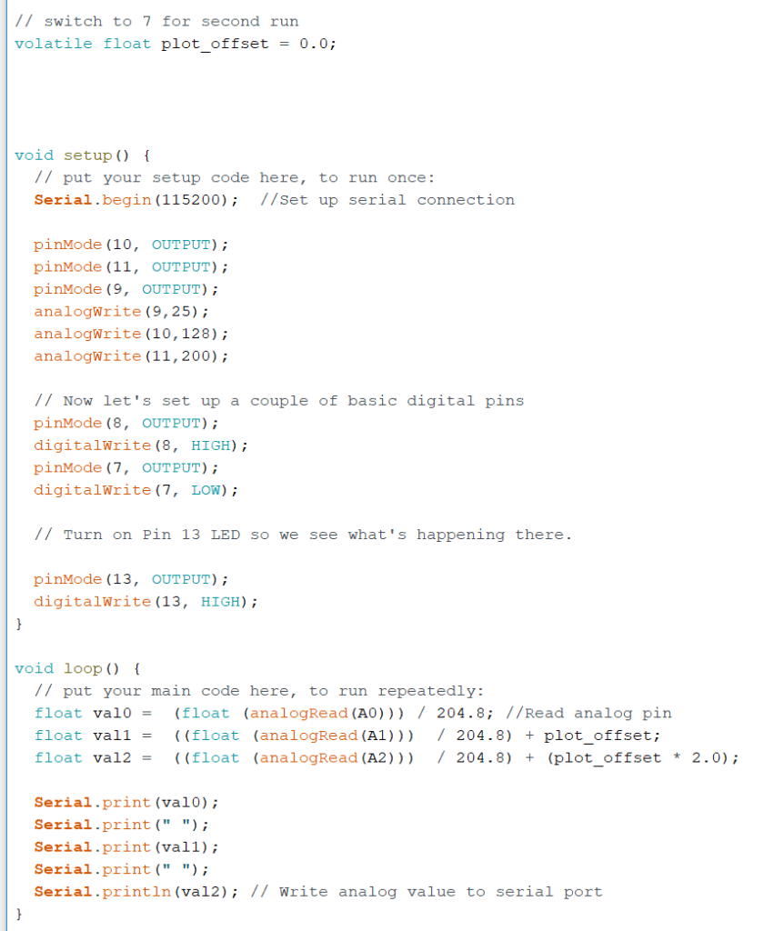
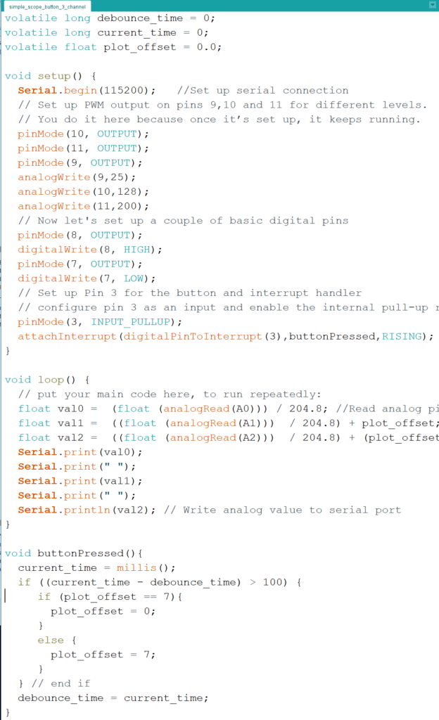
We modify our last example as follows:
- At the top, we declare a new variable plot_offset. In our Arduino 2 class, we’ll talk about why we declare it as volatile
- In our void() loop, we now have analog reads from A0, A1 and A2
- The plot_offset calculations on A1 and A2 will allow us to overlap the three plots (when plot_offset = 0), or, by setting plot_offset to 7.0, we can “stack” the plots so that they are all visible.
- If we put multiple values on the same line, our Serial Plotter will plot them separately.
- Serial.print() sends out the value without a carriage return. So whatever is Serial.print()-ed next will appear on the same line. And we need to print a space (” “) to separate the items.
- Serial.println() adds a carriage return at the end, indicating the end of the line.
Try the program with first with plot_offset = 0.0; as in the code above.
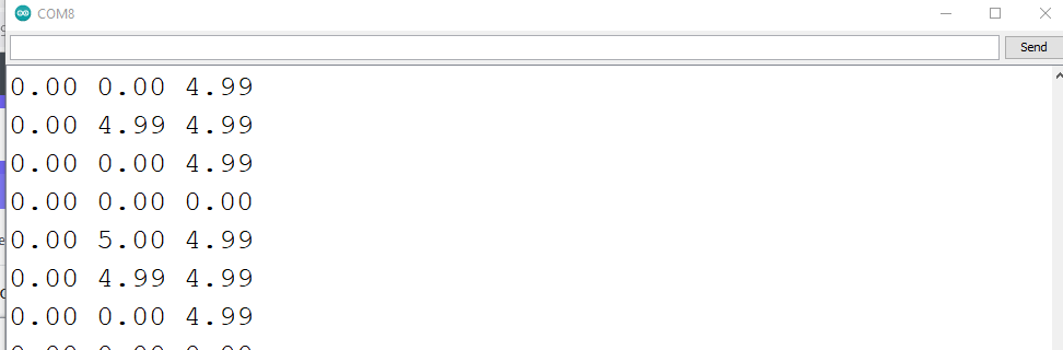
If you look at the five Serial.print() commands, you’ll notice the following:
- We separate the values with a space using the Serial.print(” “) command
- On the last command, we use Serial.println(). It adds a line end – like a carriage return – to indicate a new line
- When our serial plotter sees multiple values on the same line, it automatically assigns each one a different colour.
We can see what the output of the Serial.print() and Serial.println() commands look like by using closing our serial plotter window and using Tools ->Serial Monitor instead.
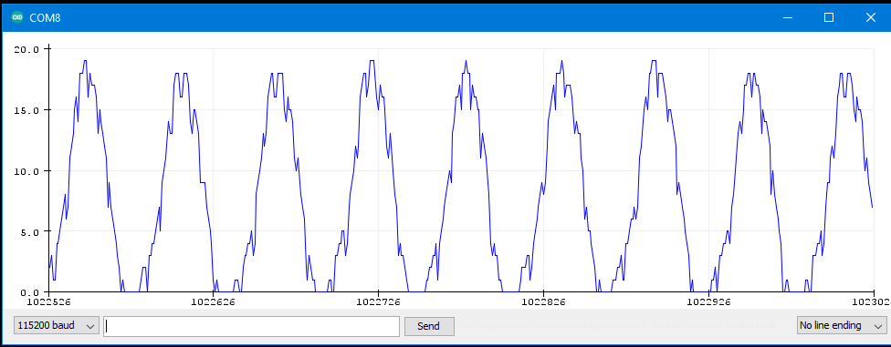
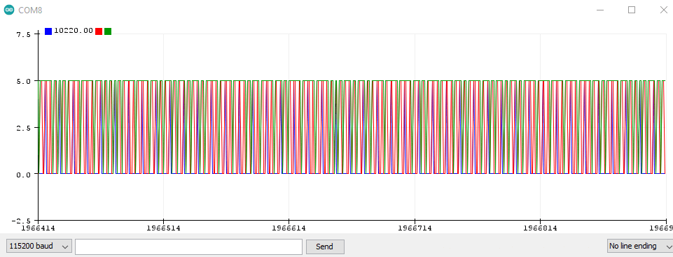
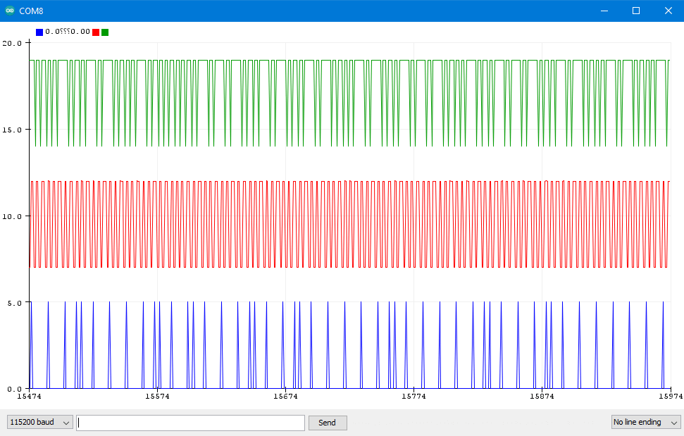
The plots overlapping are a colourful mess. Let’s stack them up.
By adding an offset of 7 to the values from pin A10, it’s range will go from 0-5 to 7-12. Adding twice the offset to the values of pin 10 will change its range to 14-19.
Then try again with plot_offset = 7.0; and see what it looks like.
Once you have this code running, you’re ready for our Arduino 2, starting in the next section.
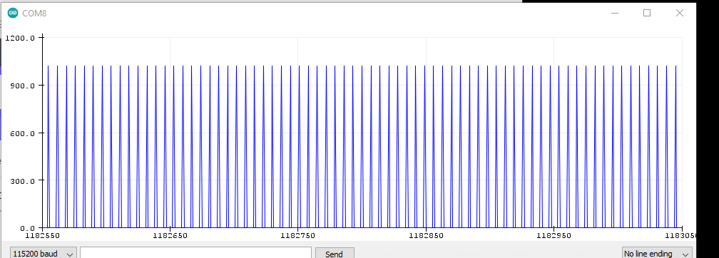
Problem: did you notice that the plots in the triple scope are sparser than the individual plots?
You’re seeing the limitation of the Arduino’s performance! Serial.print() is a fairly slow operation, having to generate characters and send them at a controlled speed over the USB cable to the plotter software on the PC.
At 16 MHz, the Arduino is certainly slower than the GHz PC chips. On the other hand, it is completely dedicated to running your Arduino sketch program. There’s no operating system, network handle or anything else running in the background. For critical tasks, it could end up running faster than your PC. Read more about Arduino performance here.
3.4 Adding a button to our oscilloscope
3.4.1 The basic pushbutton
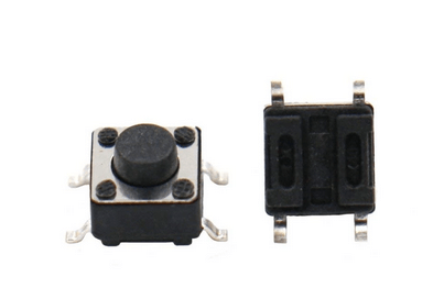
This is our basic pushbutton – on when you press it, off when you release.
The two wires on each side are connected. You can tell by looking at the underside – the vertical plastic forms on the underside show the two pins are connected.
- Pressing the button links the wires on the left side to the wires on the right side
- It doesn’t matter which of the two wires on each side you use.
With Arduino’s programmability, this button is far more flexible than an on-off switch.
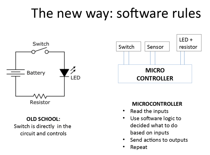
The Arduino reads the button, and can treat it however it wants. We can use it in different ways:
- We can treat it like a switch, reading as ON when it’s pressed, and OFF when it’s not pressed
- We can reverse the logic – OFF when pressed, ON when not pressed
- We can treat it as a toggle – press and realease turns ON, press and release again turns OFF
- We can treat it as a sequence – first press tiggers function A, second press triggers function B, third press triggers function C… and so on until we come back to A.
We’ll be connecting our button to a breadboard.
Take a few moments to read this excellent tutorial on breadboards.
(Waiting… you are reading it, aren’t you?)
We will hook up our button to the breadboard so that those interconnected lines on the bottom of the button are crossing over the gap in the center of the breadboard
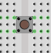
So think of it as rotated 90 degrees from the picture above.
- The two wires at the top are interconnected
- The two wires at the bottom are interconnected
- Pressing the button links the top row to the bottom row.
Why did we do it this way? Because most of the buttons won’t fit across the gap if you try and plug them in the other way. Duh.
3.4.2 Stabilising the signal: pull up and pull down resistor circuits
For out first hardware addition, we’re going to add a push button to our oscilloscope.
Problem: in section 3.1 above, we showed that there was voltage showing up on our pin even when nothing was connected. How will we know if the button is up or down if we get voltage anyway?
Problem: when pressing a button, it’s not a clean off-to-on or on-to-off change. The voltage can bounce around a bit before settling down. It’s a similar effect when you turn a light switch on or off slowly and you hear some sparking.
The first problem is solved by “pulling up” the pin to 5 volts or pulling it down to 0 volts when nothing is connected.
This video on youtube is a great explanation of how pull-up and pull down resistors work to stabilise the voltage level. Go ahead and watch it.
Next, you need to build a circuit to demonstrate both. Build the circuit and enter the code from this youtube tutorial.
3.4.3 Better button detection: introducing interrupts
What is an interrupt
So you are running your void loop() code, where you keep checking forever if some input or signal level or other reading is really necessary.
But is that really required?
Your desktop or laptop has dozens of things running. Is it looping around looking for keyboard or mouse input, or for something coming in from the Internet to update the page you’re browsing?
There’s another way of signaling events that’s built in to most computers – interrupts. They do exactly what the name says. When an event happens:
- the processor interrupts the currently running program – but remembers where it left off
- the processor jumps to pre-specified section of code to deal with the interrupt
- when that’s done, the processor returns to interrupted program, continuing exactly where it left off
That section of code the processor jumps is referred to by different names – signal handler, interrupt handler, or, in the Arduino world, ISR or Interrupt Service Routine
Types of Interrupt
Interrupts generally fall into two categories – external and internal.
External Interrupts
On Arduino – and for that matter, on computers and microprocessors in general – interrupts are triggered by a change in voltage on one of the input pins. It might be when the digital value goes from LOW to HIGH (i.e. 0 to 5 volts), HIGH to LOW (5 volts back to 0), or either one – a change from the current signal level.
These are external interrupts because they’re coming in from outside of the processor, through one of the input pins.
This type of signal change can be triggered by anything attached to the pin – keyboard, a sensor, or any number of devices.
Defining and setting up an interrupt
Interrupts are configured and managed as follows
- You create a function that will be called automatically when the signal changes on the pin. This will look like a standard Arduino function. We refer to it as an interrupt service routine (ISR) or an interrupt handler.
- We attach that function to an specific pin, indicating what change on the pin will trigger the interrupt service routine
No matter where you are in your code – somewhere in the main void loop() function, or in another function you called – triggering the interrupt on the pin will:
- pause your code and immediately jump to the ISR
- process the code in the ISR
- return to where your code left off
ISRs should be extremely brief. Remember that you are interrupting other code that may be important to keep running.
- Do as little as you can in the ISR
- Do as much as you can outside the ISR
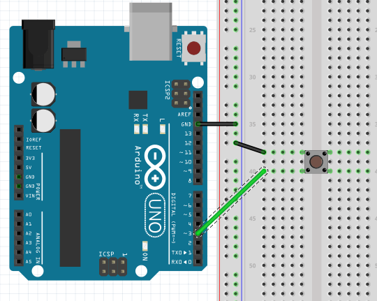
Wire up a single pushbutton like in the video tutorial of section 3.4.1 on pin 3. We’ll do it with an internal pullup resistor.
In our code example, we have Serial.println() lines inside our ISR. THIS IS TO BE AVOIDED IN REAL CODE. We have it in there to help you understand what’s happening.
He’re our code:
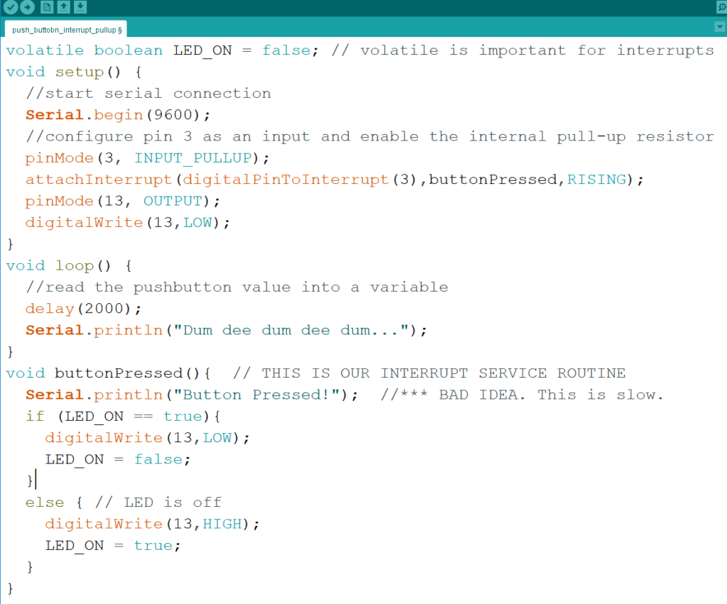
Looking at the code, we need to pay attention to the following:
- volatile boolean LED_ON… at the start of the code is defining a variable that will appear in the ISR and that needs to be remembered for the next time the ISR is run. The volatile declaration ensures that the compiler doesn’t optimise it out of the code. That can happen because the ISR function is never called by the void loop() function. The compiler may assume the ISR function is never used – even though it is declared in our attachInterrupt() command
- attachInterrupt(digitalPinToInterrupt(3),buttonPressed,RISING);
- Sets us up to watch for a change on pin 3
- RISING means the ISR will be called when the voltage goes from low to high
- buttonPressed is the name of our ISR function to be called
- void buttonPressed() is our ISR. You should be able to understand the code.
Try it out and see how it behaves.
3.4.4 Taking out the button bounce to avoid unnecessary ISR activity
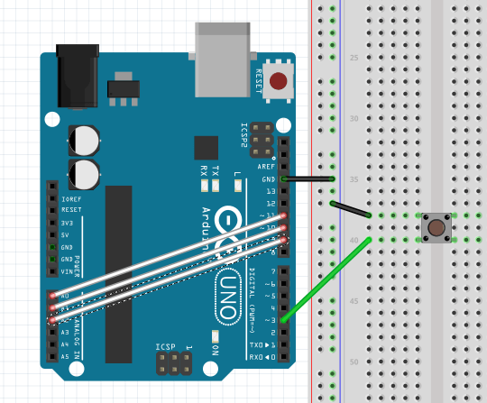
The circuit
We mentioned that the button press might not be clean – the levels can jump out and down a bit over a few milliseconds. That could be enough to trigger the interrupt handler multiple times.
Here’s our circuit:
If you read that tutorial we pointed you to earlier, you know that the vertical lines of dots on the left side are used as power and ground busses.
A couple of conventions that are good to follow for your diagrams and wiring:
- Connect the ground from the Arduino to the ground bus
- Make the ground wire black
- Anything else connected to the ground should also use a black wire
- Same rule for power – it should go to the first vertical line, and the power connection from the Arduino board and anything connected to it should use red wires
No red wire in our diagram, because nothing is connected to 5 volts. Why?
- The button is only connected to pin 3
- The built-in pull-up resistor for pin 3 within the Arduino has the connection to 5V internally to the Arduino
- If you don’t understand this, go back and watch the two videos at the end of section 3.4.2.
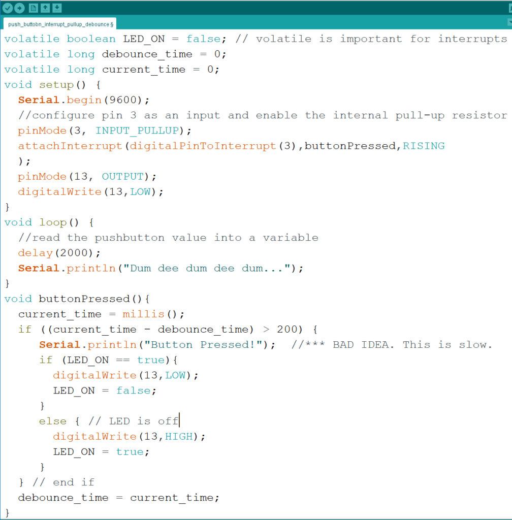
The code
We’re going to add code to ensure that when the ISR is called, it only takes action if it’s been at least a time of 200 ms (milliseconds) since the last call.
- We set up the variables debounce_time and current_time as volatiles at the top of the code. Their values need to be maintained between executions of the ISR
- Inside the ISR
- We read the current time in milliseconds current_time = millis()
- We only run the code inside the if statement if it’s been more than 200 milliseconds since thel last time the ISR was called.
3.5 Adding a button to our 3-channel oscilloscope
Let’s modify the 3-channel oscilloscope of section 3.3 to switch between stacked and overlapped traces by pressing a button.
This time, we’ll make sure we have a tight, compact interrupt service routine – the way it should be in an ISR.
- We shorten the debounce time
- All we need to do is flip the plot_offset between 0 and 7 each time the button is pressed.
That’s it for Arduino 2.
You can read more about interrupts in the official Arduino documentation.
Things to read while waiting for Arduino 3:
Want to get ahead on Lesson three?
Here’s the material we’ll use for the ultrasonic range sensor
4. 0 Timer Interrupts
There are some key concepts you need to understand for using timers inside an Arduino – or any other microcontroller.
- There are a limited number of timers – only 3 in the Arduino
- The timers are shared for many things. Those PWM cycles on the pins? Timers. delay() and millis() functions? Timers. Some libraries you may use? Timers. You can’t just stomp all over the other stuff.
- There are limits on how long a timer can be, and how precise they are. But they are pretty darn precise.
4.1 Timer limits, precision and sharing
4.1.1 Understanding the processor speed and clock ticks
On a simple microprocessor like the 16MHz Atmel microcontroller of the Arduino:
- 16 MHz means 16 million “clock ticks” per second
- Actually a bit more than 16 million. It’s 2**20 = 16,777,216
- Each clock tick is 62.5 ns (nano seconds – billionths!)
- A single instruction is run every clock tick
- There are exceptions
- Complex microprocessors may have instructions taking more than one clock tick
The internal “timers” clock from register that:
- Start at 0
- Count up to a maximum value every clock tick
- Cycle back to 0
The three Arduino timer registers are:
- Timer0: 8 bit -> maximum 256 ticks (0 to 255) -> maximum timer duration: 16 microseconds
- Timer1: 16 bit -> maximum 65536 ticks (0 to 65535) -> maximum timer duration: 4.096 milliseconds
- Timer2: same as timer0
That’s not very long at all!
4.1.2 Extending the clock limit: control registers and pre-scalar values
We can extend the clocks using a prescalar value that says to only update the clock register every X ticks (the prescalar value) of the main system clock.
The prescalar value is set in a timer clock control register (TCCR).
For each Arduino timer, there are two of these control registers.
Let’s have a quick look at the two registers for timer1: TCCR1A and TCCR1B
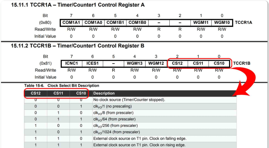
The three bits on the right of TCCR1B control the prescalar value, and from the table, we see that the possible values are 1 (no prescaling), 8, 64, 256 and 1024.
The labels on those bits – CS10, CS11 and CS12 are, coincidentally, handy constant values in the Arduino IDE programming language. We’ll get back to those later.
We put together the following table to show the clock granularity and maximum timer value for the 8 bit (timer0 and timer2) and 16 bit (timer1) timers.
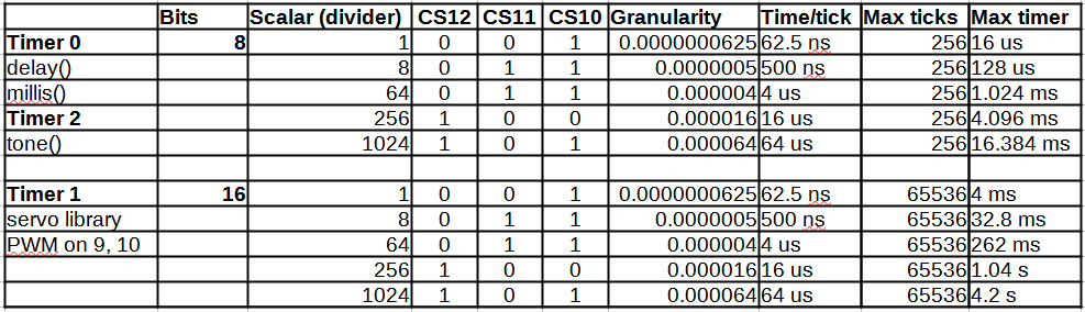
So our absolute maximum timer duration for the 8 bit timer0 and timer 2 is about 16 milliseconds, with a tick granularity of 64 microseconds.
timer1, at 16 bits, gives us an absolute limit of just over 4 seconds, with a timer granularity of 64 microseconds.
These values are incredibly fast and precise. In a tight process control environment, a dedicated-to-one-program 16 MHz microcontroller can respond faster and more reliably and consistently than a monster 4 GHz processor running an operating system and a ton of overhead.
4.1.3 Timer sharing – a big gotcha. Or not.
The three timers we’ve described are accessible to you as a programmer. But they are not exclusive to you. Before using a timer, it’s important to check if it’s being used by anything else.
Our table 4.1 above mentions some common features of the Arduino that use timers:
- the delay() and millis() functions use timer0
- PWM on pins 9 and 10 and some libraries like servo control use timer1
- the tone() function uses timer2
There are many other functions of the microcontroller that you think use the timers – but don’t. That’s because the microcontroller has other internal timers and functions. Serial port communication on the USB bus is an example. It requires precise timing to control speeds from 9600 baud to 115200 baud and above. Commenter TCWorld writes:
There are other timer-like things inside the Arduino’s microcontroller but they are used by other things.

If you are using a library and want to use timers, check the documentation to see if you might be interfering.
4.2 Programming a timer
You will find a lot of coding examples of timers on-line. Their code and calculations often looks like confusing gibberish.
Here are some pointers to help you out.
4.2.1 Choosing a timer
Example : 1 second timer
1. First, we check our table 4.1.
Max timer for timer0 and timer1 is 16.384 milliseconds. Not enough.
Max timer for timer 1 is 4.2 seconds. That’s more than enough.
2. Check for timer interference
Does our code use PWM 9 or 10? Do any of the libraries we need use this timer?
3. Select the prescaler and calculate the number of ticks
From our table, we have three options that will give us at least 100 ms:
- Scaler 64: 011: 262 milliseconds max, 4 microsecond ticks
- Scaler 256: 100: 1.04 seconds max, 16 microsecond ticks
- Scaler 1024: 110: 4.2 seconds max, 64 us ticks
It’s all about precision – is close to 100 ms good enough, or do we need an exact-as-it-can-be timing?
Let’s go with option 3 – scaler 1024
For 1 second, we need 1 second / 0.000016 microseconds = 15625 clock ticks
4.2.2 Timer interrupt types: Compare, Overflow, Input Capture
Our 1 second timer will be a compare. Here’s a description of compare and the other timer options:
Compare:
- Calls the interrupt handler when the clock counter reaches a value
- We have to set the value in a register (we’ll get to that later)
- Important: if you want to keep repeating the same timer interval, you need to reset the counter to 0 yourself at the start and each time your interrupt handler is called.
- Each timer supports two separate compare values
Overflow:
- Calls the interrupt handler when the clock counter reaches its limit
- 255 for 8 bit registers
- 65535 for 16 bit registers
- Clock is automatically reset to 0 and starts climbing again
Input Capture
- Calls the interrupt when a signal change happens on one of the pins
- Save the timer counter value so you know when the interrupt happened
4.2.3 Registers and constants
For each of the timers (0, 1 and 2), you have the following registers, where x is the timer number:
- TCCRxA: Control for PWM timing and other things
- TCCRxB: Control that includes our three prescalar bits CS10, CS11 and CS12
- TCNTx: The counter register. You can set it to zero or whatever you want as long as it is within the allowed range.
- 8 bit (timer 0 and timer 2): 0 to 255
- 16 bit (timer1): 0 to 65535
- OCRxA and OCRxB: Compare registers to set the comparison value for a COMPARE interrupt
- This is cool: we can have two separate compare values for each timer!
- TIMSKx: Register to controls the timer type – OCRxA, OCRxB comparisons, or overflow (reaching the max counter value)
TIMSKx looks like this:
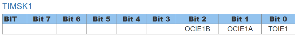
Each bit enables as follows:
- Bit 2 for comparison against OCRxA
- Bit 1 for comparison against OCRxB
- Bit 0 for overflow
- Those values (OCIE1B, etc) in the boxes are constants.
We have constants to help us set the values in the registers
- CS10, CS11 and CS12 are value 0, 1 and 2 to point to the (from the left) first, second and third bits of register TCCRxB for setting the prescalar value.
- OCI1EB OCIE1A and TOIE1: same deal as CS10, CS11 and CS12 above for TIMSK1
Next section tells you how to use these constants for setting the registers.
4.2.4 Setting the prescaler value
In the preceding steps, we decided that we will use:
- timer 1
- prescaler 1024 (101, or CS12=0, CS11=0, CS10 =1)
First, we zero out the two control registers for timer 1
TCCR1A = 0;
TCCR1B = 0;
Now we’ll set the bits. It’s an 8 bit register. We can do this in one of three ways, going from easiest to hardest and most precise.
- Option 1: set the whole register directly
- TCCR1B = B00000101; // B means a binary value of 1s and 0s. Notice that we have 8 bits.
- Option 2: just set the bits we need
- This is a better option because in some circumstance, we may be using some of the other control bits
- TCCR1B |=B00000101;
- The |= operator means ” do a logical OR of myself (TCCR1B) and the value on the right.
- Option 3: Use the constants to set the appropriate bits
- This is the best option for long-term and portability. Because the bit positions might change. Unlikely, but possible
- TCCR1B |= (1 << CS12) | ( 1 << CS10);
- We are again doing a logical OR against TCCR1B with the |= operator
- CS10 and CS12 are 1, and we’ve already zeroed out the register
- << is a bit left shift operator
- It starts with value 1 (which would be B00000001), and shifts is left by CS12 bits. That gives us B00000100
- At th other side, we start with value 1 and shift it less by CS10 bits… which is probably zero… and that give us B00000001
- We logical OR them together to give us B00000101
- It does a “logical OR” of that value into TCCR1B
4.2.5 Setting the compare register
We have two choices for timer 1: OCR1A or OCR1B. We’ll go with A.
OCR1A = 15625; //We calculated this earlier for 1 second.
Now we need to enable compare interrupts for the value in OCR1A.
Options below have the same reasoning as preceding section for the scalar bits
- Option 1: TIMSK1 |= B00000010;
- Option 2: TIMSK1 |= (1 << OCIE1A);
4.2.6 Key timer interrupt functions and operations
- nointerrupts(); // Pause all interrupts. Older versions have cli()
- interrupts(); //Enable interrupts. Older versions have sei()
- TCNT1 = 0; //Set the timer counter for timer1 to zero
4.2.7: Setting up the interrupt handler function
All timer interrupt types use the same ISR() function.
It’s different from other functions. We can define it multiple times, each time with a different VECTOR to tie it to the correct timer. The vectors are:
- TIMERx_COMPA_vect – for timer x, compare register A
- TIMERx_COMPB_vect – for timer x, compare register B_
- TIMERx_OVF_vect – for timer x, counter overflow
We are using timer1, compare register A, so our function will look like this:
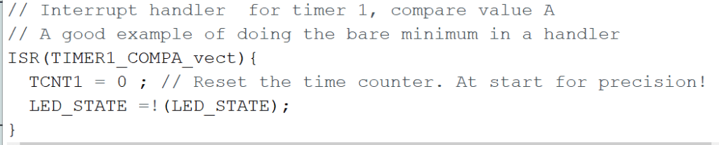
We put as little as possible in the interrupt handler.
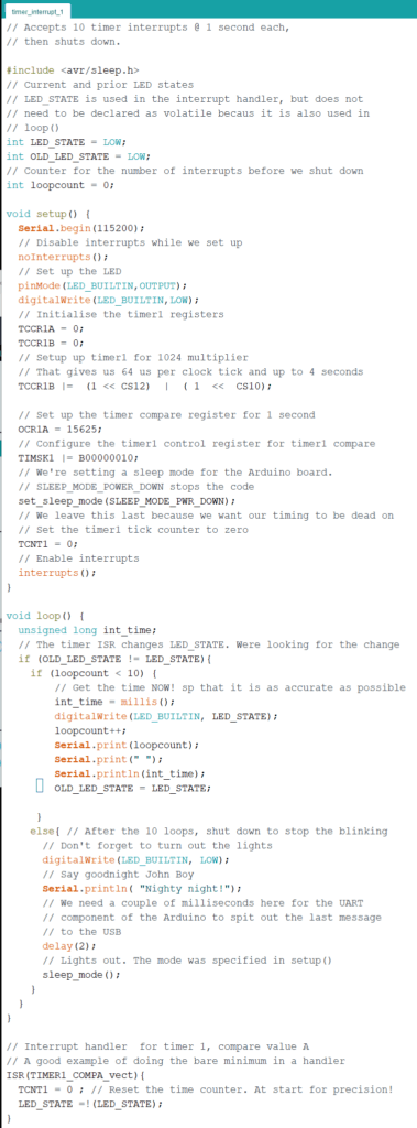
4.2.8 The code: accept 10 timer interrupts, then go to sleep
We’ve added a few things to this code so it doesn’t run forever.
Open the Serial Monitor before running it, at the same baud rate (115200) as the code.
Our Serial Monitor output looks like this:
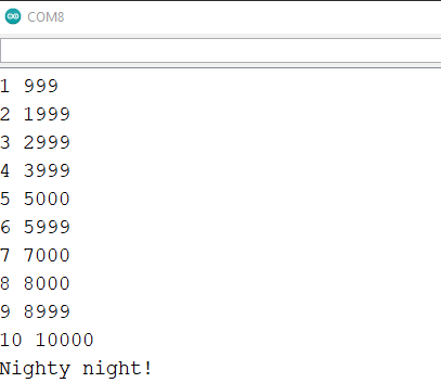
Notice how precise the timers are – always within a millisecond of what we expect.
5. Using libraries for devices
To make things easier for programming, many devices come with libraries that handle the nitty-gritty of timing, interrupts and configuration.
If you’re trying to program for a device, get the model number and start a web search. You’ll be surprised what you find.
In this section, we’ll look at a popular range finding device and the difference between coding for it yourself and using a library.
Lucky us – we don’t have to write much. A couple of other sites did a really good job on this one.
5.1 The HC-SR04 distance/range sensor
5.1.1 Power requirements

First thing we want to do is check out the spec sheet.
There’s an excellent overview here with links to full spec sheets and some of the key details
A question you should ask for any device you’re hooking up: does it need external power, or can it draw from the Arduino?
The page tells us it’s working current is 15 mA.
Arduino output current ratings from this excellent page are:
- Maximum total when connected to USB: 500 mA
- Maximum for each I/O pin: 40 mA
- Sum of all input/output pins (not including 5V out): 200 mA
We’re good – Arduino can easily provide the 15 mA required.
5.2 Writing your own code vs using a library.
This Random Nerd Tutorial we found by searching has everything you need to know, including:
- How the HC-SR04 works
- How to code for it
- How to code using a library that does the heavy lifting.
Go to the tutorial and come back smarter.
There’s really nothing else for us to do on this one.
Further Reading:
Arduino programming language reference
Atmel documentation on the Arduino’s processor, the ATmega328