Laser Cutting and 2D CAD with QCAD
Goals for the class
- Learn enough to create your own graduation plaque
- Basic shapes
- Text
- Images
- Creating a laser-ready file
- If you follow our instructions, we’ll have time for:
- Making multiple name badges
- 3D box structure design
Reminder: non-commercial, low-volume use only
- We tolerate making prototypes for your small business… if you are not hogging the machine
- If you’re going to sell it, it’s forbidden
- Low volume for non-profit groups OK – your Scout group, small school club, etc.
- High volume (whole class, 200 kids at Scout camp, etc.:
- Prototype here
- We can refer you to a great commercial place to run the job
CAD Program: QCAD
- Free version – it has limits but we can work around them
- 30 day trial period has full PRO version features
- Automatically downgrades to free version after trial
- C$50 gets you the PRO version – and it’s worth it – with a year of updates
- Download here
- Professional interface
- But not as compatible with AutoCAD as DraftSight and nanoCAD – but you can work it
- Other 2D CAD programs we looked at:
- Draftsight – no longer free; now annual fee
- nanoCAD – free version limited and no longer updated – it’s many versions older than the paid product; now annual fee
- LibreCAD: too many bugs and too little development happening.
- Other free programs not comparable
- Note: we’re talking about full AutoCad and not AutoCAD Fusion 360, which is completely different interface.
- Limitations of free QCAD version that we care about for laser cutting”
- Only supports saving in an older version of .dxf file. But that version is compatible with our laser cutter. If you need another format to import or export, download this free ODA File Converter.
- “Offset” only works on single elements, not on a full object. Don’t worry – we’ll explain what that means later. Not a big deal.
On the free trial, the PRO version will run for 15 minutes at a time – but it’s really nice about it, asking you to save your work which you can then re-open.
To enable the free version and stop the 15 minute restarts, you need to manually remove files as directed on this screen by pressing the Trial button on the right.
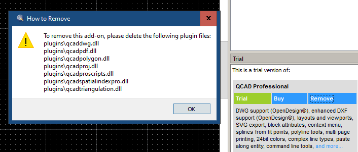
If you followed the default installation process, the files will be located in C: \Program Files\QCAD\plugins.
If there is any chance you will pay for the PRO version, then instead of deleting the files, create a directory deleted_plugins and move them there. Or just do a full reinstall.
Parametric Interface
- We want you to use this because:
- It’s more accurate faster than clicking around with a mouse
- Once you learn it, it’s faster. Incredibly faster for repetitive task… which is most CAD work.
- Same interface as the major commercial programs
- This is what we’ll be teaching
- Learn it, and you’ll work faster and more accurately
Parametric command sequence: command first, click (if required) later
- Enter command
- Follow instructions to enter parameters
- Follow instructions to select target(s) for the command
- Repeat step 3 to hit multiple targets.
We’ll have lots of examples – and you’ll get used to it.
QCAD adds a few twists
- After entering some commands, option box appears at top. Watch for it!
- Some options like “snap” features can be changed from menus while in command
- Multiple items selected with shift-click (most programs use ctrl-click)
- Not as consistent as the AutoCAD compatible programs
- Those are always command first, select what to run the command on after
- QCAD mixes the two.
Laser cutting program: Your design -> laser cutter commands
- Requires security dongle to operate
- We keep it locked up.
- Runs on PC beside laser cutter
- You load your stuff with USB stick
- Does checking on your design to make sure it’s OK
- Primarily for engraving to ensure loops are closed.
- Minor editing possible
- Fix your stuff on your CAD program
- If you sit there hogging the machine to fix your design, anyone can boot you off.
Cutting vs Engraving
In CAD:
- Just enter your design
- Separate the cut and the engrave parts in layers of different colours
In LaserCut (our laser cutter program):
- It recognises the layers
- Configure the layers for cut or engrave
- Configure the laser parameters for each
- You can have multiple cut and multile engrave layers
Cutting: cuts through the material
- The last part – because the material comes lose after it’s cut out
- One pass gets through
Engraving is a raster process (like old dot matrix printers)
- Starts at the bottom one one side
- Scans across. When it hits a line in the drawing layer, it turns on laser
- When it hits the next line, in the drawing, it turns off the layer
- Critical for everything being engraged to be in closed loops
- LaserCut checks for that
New for latest class: Engrave cut
- Same as cut, but lower power
- Just enough to engrave
- Use if you just want line drawings, letter outlines
DEMO TIME: Let’s see how all this works on the laser cutter
File formats
- .dwg :
- Default for AutoCAD and compatible programs like DraftSight.
- QCAD: Only available in PRO
- .dxf : Multiple versions!!!
- usually AutoCAD 2013 format)
- It’s what LaserCut supports
- QCAD PRO supports it
- QCAD handles it fine but…
- You have to set up the layers properly. It’s tricky in QCAD
- Don’t worry. We cover it for you in this lesson
- You have to set up the layers properly. It’s tricky in QCAD
- AutoCAD and Draftsight require dxfexport command
- nanoCAD supports 2013 dxf as native format
- usually AutoCAD 2013 format)
.dxf is always in metric (mm), so for consistency and accuracy, try to make your drawings in mm.
Basic CAD principles
Measurements and scale
- Stick with metric as much as possible. Draftsight defaults to metric. It will translate through nicely. NASA learned this the hard way after screwing up some billion dollar spacecraft.
- but… if using something already drawn in imperial units, stick with at. You can convert as a last step
- Draw twice – if the first time is on paper.
- It will help you get your thoughts down and your basic measurements in place and calculated.
- It will save you a lot of time.
Starting QCAD
First thing for any drawing: setting our dimensions.
Edit -> Drawing Preferences -> General -> Drawing Unit
Make sure it’s millimeters and metric and you can’t go wrong.
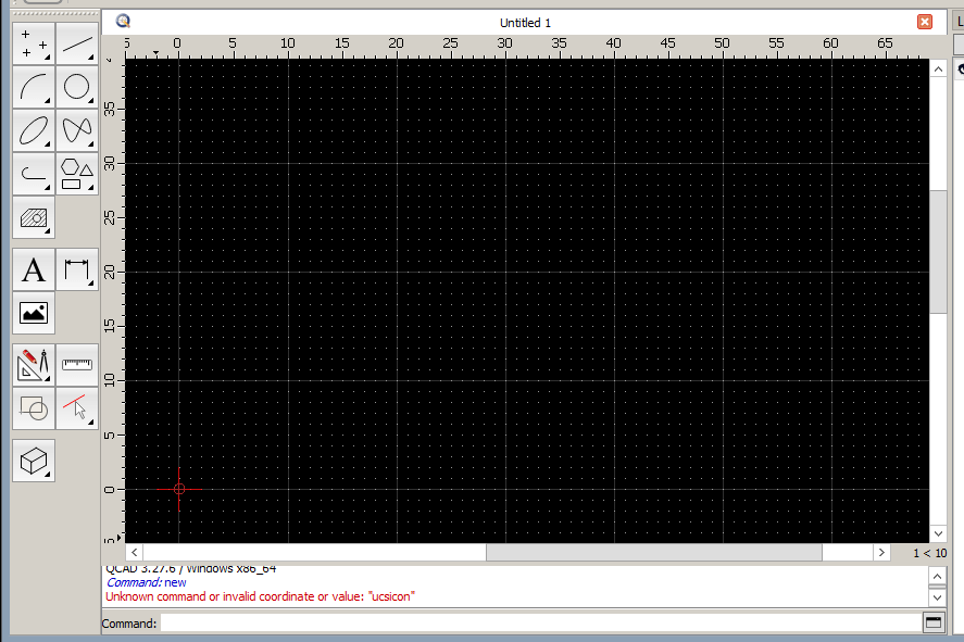
(0,0) coordinate
That red target near the bottom left corner is position X=0, Y=0, or (0,0). You can see it on the scales on the side and top of the grid. Just like those cartesian coordinates you learned in school.
You can draw to the left of it or under it – but avoid doing that. When you import your drawing into the laser cutter, (0,0) is the bottom left of the laser cutter. Keep that in mind and you will have fewer corrections to make later.
Icons… or command window
A key feature of professional QCAD programs is command line entry. If you learn it, you will be able to work faster, and you can more easily move between CAD programs.
QCAD is not as compatible with the AutoCAD command as other programs like Draftsight and nanoCAD – but we nevertheless recommend you use the command line interface.
Type rectangle in the command line box, and you get prompted for what you need. We’ll draw a 50 mm wide by 20 mm high rectangle.
After entering the command, it immediately prompts us for the first corner. We want it at 0,0.

After hitting enter, enter 50,20 as the second corner.
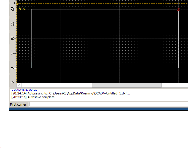
Looking at the command window on the bottom… it wants to keep drawing more rectangles, asking you for the first corner of the next one. Hit ESC to get out of that.
Unlike hand drawing, we know that:
- We have a rectangle that is EXACTLY – not approximately – 50,20
- We know that it is located EXACTLY at 0,0, so we can draw things relative to it
Note: QCAD and most CAD programs will accept NEGATIVE dimensions.
- -50 would position the rectangle to the left of 0,0
- -20 would position the rectangle below 0,0
Go ahead and try it – but wrap it up with a rectrangle 50,20 rectangle at 0,0
Pro command window tips:
- you can back out of multiple commands with CTRL-Z
- you can retrieve prior commands with the up and down arrows
Relative co-ordinates
Let’s draw a second rectangle immediately to the right of the first one.
We know the starting position will be 50,0. But what will the opposite corner be?
Instead of calculating it, we make it relative by putting in the same size as follows:
- @50,20
Without lifting a hand from the keyboard, this can all be done in the command line window as follows:

Did you spot the rectangle option box at the top?

- Polyline: Do you want it treated as one object (rectangle), or as 4 separate lines?
- Other CAD programs always make it a polyline
- You can split it up with explode (XP), and re-unite with block (BC)
- Radius: Used to round the corners
- Fill: pointless for laser cutting. Don’t bother
Moving an object
- Select what you want to move. Remember: shift-click to select multiple.
- Hover your mouse over different parts of the rectangle to see the snap points
- Middle of lines
- Corners
- Any point in the grid
- Click on the snap point you want to use. The move/copy will be to the same point
- Move to the new move/copy point
- Click and a menu appears

Multiple copies will always appear in sequence from where you clicked.
Resizing and repositioning the drawing surface.
Resizing and repositioning is done with the mouse scroll wheel. It works as follows:
- It’s always relative to where the mouse pointer is located.
- Scrolling down shrinks the drawing towards where your mouse pointer is located.
- Scrolling up enlarges the drawing away from where the mouse pointer is located.
- The farther the mouse is from the object, the faster it moves across the screen.
- If your mouse is in the center of the drawing, it shrinks or enlarges around that point
Take some time to get used to this movement. It will become natural for you.
- One at a time, move the rectangle to each of the four corners of the drawing window
- Move the rectangle to the center and make it as small as possible
- Now make it as large as possible in the drawing window
Keep playing with it until you are comfortable with the motion.
SNAP: Positioning your next steps relative to existing points
Just like the way we positioned our rectangle at EXACTLY 0,0 and gave it an EXACT size of 50×30, we want anything else we add to the drawing to be just as precise.
In other CAD programs:
- On/off buttons at bottom of screen
- Detail settings under Tools -> Drafting settings
In QCAD:
- Everything in the Snap menu
- You can navigate to the Snap menu while drawing
- You can see the commands in the command window if you want to avoid the mnu
Snap and grid:
- Snap -> free or grid to snap to grid or not
- snap to snap to grid
- But some find these annoying
osnap (object/object key point snap):
- far more useful
- snaps to corners, centres, midpoints
- otrack extends lines to click to them
- If you specify centre in the Drafting Settings, works for circle or portion of circle
- Horizontal, vertical or orthogonal (both) restrictions
Simple exercise: draw exactly centred horizontal and centre lines in the rectangle
Snap > auto
Command window: line
- Now move the mouse near the center of the bottom of the rectangle… and it guides you to click to the correct point. Repeat at the top center of the rectangle, and you have a line of the perfect length at the perfect position
- The command window wants next point… because it wants to draw from the end of the first line. We don’t want that. Hit ESC and now it asks you for a new first point. Repeat steps above for the horizontal line.
Polar (angles)

- Snap -> Polar coordinate brings up menu bar above
- Specify line length (r) and angle (<:)
- When it’s on, tracks to centre and selected angles (turn all on in settings)
- Great for hitting 45 degree angles on a circle
Ortho: only vertical and horizontal lines
WHY SNAP IS IMPORTANT
Big gotchas:
- overlapping lines
- not-quite-connected line
- over-connected (crossing) lines
This hand-drawn rectangle looks fine – but is it?

Zoom in on the top right corner, and we see…

And on the bottom right corner, we see

BOTH OF THESE WILL CAUSE PROBLEMS ON THE LASER CUTTER!
You might not see them unless you enlarge way more than you expect!
Example: you draw two rectangle boxes that abut each other. The sides are an exact overlap
This is bad. Laser will try to cut twice!
Two options:
Method 1:
- Explode the second rectangle
- delete the duplicate side
Method 2: Draw it withouth overlapping rectangle
- Draw the remaining sides of the rectangle as separate lines.
- Draw a bigger rectangle and a line to divide it
Deleting stuff
Opposite of the other CAD programs – first select, then delete
- Select everything you want to delete
- Click individual items
- Or: click/drag over area with mouse
- Or: both!
- Enter delete command or hit the DEL key
Offsets, Explode and cut lines
Offset
Incredibly useful for:
- Creating new or temporary osnap points
- Repetitive tasks – which is a lot of CAD
- Modifying shapes
BIG DIFFERENCE BETWEEN FREE QCAD AND PRO:
- QCAD free will only offset individual elements (line, circle, arc, etc.)
- QCAD PRO will offset full polyline shapes
Draw a 60 x 30 rectangle
Command: offset

- Distance: specify 5 (5 mm)
- Number: leave it at 1
- Polyline mode: just the segment you are on, or the full object?
- A side of the rectangle – or the full rectangle?
- QCAD: this is different from other CAD programs – you can select one element or the full polyline
- To just do a segment in other CAD programs, you would need to explode first
- In QCAD, even if exploded, it still recognises a polyline!
- object to offset: Use mouse to select the object
- Spefify point on side to offset:
- Do you want your offset inside or outside? Click the side you want!
- Keep repeating: click to select object, click to select which side you want the offset

Works with circles – great for drawing bulls eye! Try it!
- Can you guess the command to draw a circle?
explode and block: you only want to break an object into its elements
Command: explode
- Select your outermost rectangle
- Menu: Block -> explode
Scroll your mouse over a side of the outermost rectangle… and only that side highlights. You have “exploded” your rectangle into four separate sides.
Command: blockcreate or bc to re-unite the lines into one shape (Menu: Block -> Create block from selection)
- Will also work with that inner rectangle with all the vertical lines
- Any “blocked” item requires a name – because CAD programs assume you might want to re-use it.
Offset and Copy – For positioning and repeating
Example: rectangle with mounting holes
Goal: 60×30 rectangle Mounting holes 2 mm in diameter, centered 5 mm from each side

- rectangle
- offset 5mm inside (for free QCAD, you need to offset each side of the rectangle)
- circle centered on top left corner of inside offset rectangle
- copy the circle (select and copy command, or ctrl-C)
- Multiple copies on a single command!
- click on the next corner of the inner rectangle
- Hit CTRL-V
- Click on the corner to paste it there
- ** and click on the other two corners!
- delete the inner offset rectangle (for free QCAD, delete each of the offset lines)
Cut lines as temporary markers
draw a 5 mm circle at exact centre of our rectangle
- line to draw a line from top-left to bottom right corner
- line again to link the other two opposite corners
- Now X marks the spot for the center of our circle
- circle
- delete to remove our two diagonal lines
Trim and Extend – cut lines
Turn our center circle into a semi-circle – and back again
- line from top to bottom of centre of rectangle – splitting our circle in half
- The snap will give us the exact center of the rectangle top and bottom

Round out the corners: fillet
Command: round or r (in other CAD programs, fillet)
- Radius: (box appears at top to enter) distance from corner to start curve. Will be same on both sides
- Select first side
- Select adjoining side
- KEEP REPEATING THE OTHER TWO STEPS FOR EACH CORNER – WITHOUT RE-ENTERING THE COMMAND
Refresher: General command usage rules
- First decide what you want to draw (line, circle, text, rectangle, etc)
- Have your dimensions ready
- Enter the command
- Answer the questions – let it do the work for you!
- Options for position (absolute or relative co-ordinates)
- Options for sizing (dimensions or second co-ordinates
- Options can be extensize.
- Text: alignment V/H, justification/centering, font size, kerning
- Options can be repetitive
- Multiple object selections for same command
- Multiple targets for copy command
- ESC to back out of current command
- CTRL-Z to undo commands
QCAD CHEAT SHEET
Shortcuts can be entered outside of textbot while drawing – try RN for rounding corners.
dimension lines
You forget how big something is… or you just want to measure.
Use Dimensions from the top menu bar
- For most lines, Aligned is the right choice. 3 clicks
- Click one corner of your rectangle
- Click on opposite corner
- Pull away from rectangle until line is where you want it and click
- Repeat above for other dimention lines!
- You can pick more specialised option depending on the shape you want to measure

but I can’t read the size on the dimension line – or it’s huge!
- The font might be so small that it’s illegible, or too big relative to drawing
- It defaults to 2.5 mm
- If you have a big drawing in your window, it’s scaled too small to read. Easiest way to fix:
- Right click on the dimension line. The Property Editor box on the right shows you the size (Text height) – you may need to scroll down to see it.
- Edit it in the property box

Text and images in CAD – most paid programs
We have a problem here
- All CAD programs (Draftsight, AutoCAD, nanoCAD) insert text as actual text
- The LaserCut problem can’t handle text – it will come up blank when you import
- Inserting images is the same. QCAD only links to the original file – and that link doesn’t carry to the laser cutter
Handling text: QCAD, Draftsight, AutoCAD and paid versions of nanoCAD Plus
- You have to vectorize the text for laser cutter to accept it
- But: **Vectorized text is no longer editable!
- **Upgrade/Paid versions of these programs
- Recommended sequence:
- Finish everything in your drawing
- Save the file (my_cad_file.dwg)
- Run the explode (QCAD) or explodetext (other programs) command to vectorize the text
- Save the file under new name my_cad_file_exploded.dwg
- For any additional edits:
- Edit the first saved file my_cad_file_dwg
- Repeat steps 2,3,4
Handling drawings – or text in other free CAD programs
For text:
- Create the text in a font in your favourite word processor
- Go to a larger fond size to have more detail
- Bold is good if you are engraving
- Snapshot the font to a .png or .jpg image

For text and images:
- Go to one of these websites:
- Upload your image and download as .dxf

In nanocad: Open a new tab and import the image
- Big gotcha: it might be HUGE… so huge that it’s off of your screen. Especially if you use a big font like we recommended.
- Use scroll mouse to shrink it down until you can see it – and add a vertical dimension line

- 117 mm in our example! Way too big to fit in our box
- Examine the text carefully – if engraving, make sure all loops are closed.
- Use scale command to get it to the size you want
- At this point, you should be able to figure out how to use the scale command
- If not… video here
- We’ll scale ours down to 10% of original size… or .1 scale factor
- Create a new dimension line to verify the size
- To cut and paste it into our rectangle i.e. between the two tabs:
- Select with the mouse
- CTRL-C to copye
- Move to tab with the rectange and CTRL-V

Layers for control
What are we cutting? What are we engraving?
In our last image above, the dimension lines are green, and what we drew is white.
The colours are controlled by layers – and the laser cutter uses the colours to differentiate.
Major gotcha in QCAD:
- The laser cutter ignores the QCAD layer colours! In other CAD programs, layer colours work fine.
- In QCAD, you have to assign a colour within the layer.
- You can assign different objects within a layer different colours – but we don’t recommend doing it that way. Managing things by layer is easier.
So we need to differentiate our text for engraving from the cutting.

Layers for control
What are we cutting? What are we engraving?
In our last image above, the dimension lines are green, and what we drew is white.
The colours are controlled by layers.
You can view and edit layers with menu View -> Layer List

We can edit the layer of an object directly in its properties by clicking the little box next to the Layer box. You can change the layer – or even create a new one.
In QCAD, in the box below the Color box is the one we need to get the colors to the laser cutter.

Unfortunately, the Color is often assigned per drawn object, not for the whole layer
The best way we’ve found to manage this:
- Place things on the correct layer. It’s OK to have a colour for the layer
- When done drawing, do this for one layer at a time:
- Hide all the other layers (click on the eye icon for the layer)
- Select everything in the layer
- Assign the colour you want in the properties box.
DO NOT USE RED AS A LAYER COLOUR!!! When you export to the laser cutter, it shows errors in red. If you use red, you can’t tell the difference between your drawing and the errors!

Important: Cutting order for inside cuts

You are cutting out a large rectangle, with a smaller rectangle-shaped hole in the middle.
It’s important the the centre hole be cut first. Why? Because if you cut out the large rectangle first, it might move a bit.
The laser cutter software is not quite smart enough to prioritise the inside cut.
So how to we handle this?
- Make the inside cut a separate layer – i.e. a separate colour
- When you get to the laser cutter software, order the cuts (by colour) so that the inside parts are cut first.
Avoiding burn marks around engraving
On wood and MDF, you will frequently get slight overburn on your material.
To avoid this, cover your material with masking tape, and peel it off after.
Assignment: Class Graduation Plaque
- Exactly 136 mm X 50 mm
- You can lay it out however you want within that size. Must include:
- Ylab logo: get it from here
- Your name
- Graduation date
- Mounting holes: exactly 2mm diameter, centered 3mm from edges
- TWO SEPARATE CUT LAYERS:
- Holes
- Frame
- Bonus points: add an image or logo
- Find some simple black-and-white clip art
- Vectorize it using the same process we used for text

Before saving, remove all the dimension lines
Importing images
The problem: unexploded text and regular (unvectorized) images won’t show up when you import them to the laser cutter
- We know how to explode text, and we can do it inside some programs
- Images must be vectorized before bringing them in
- Our ylab logo was already vectorized
- Our favourite free way to vectorize an image:
- http://vectorization.org
- Be sure to export as .dxf
- Open the image in a separate CAD window
- scale command to bring it up/down to size required – USE THE DIMENSION LINES!
- copy and paste into your drawing
Engraving negative images
Draw a rectangle or circle around your image.
Instead of the image being burned out, all the area outside of the image but within the circle or square will be burned out.
Yeah, yeah, we should add some pictures here.
3D Structures
- You can draw them flat
- But… best to learn by looking at examples
Arduino and Raspberry Pie cases: Just google
- If you want something different… start with a box and modify
- MakerCase: This site gives lots of options and dividers
- Measure thickness of your material for accurate dimensions
- Make sure to note if dimensions are internal or *external
- Adjust your dimensions accordingly
Gluing your 3D structure together:
There are adhesives that work best with each material
- Wood and MDF: Use regular white carpentry glue. AVOID GORILLA GLUE!!!
- Acrylic/plexyglass: there is a specific solvent glue that binds the pieces beautifully.
On to the laser cutter
It lost its mind. Absolute-ly. Immediate fix.
At some point in the last few months… we don’t know why… we tried all the settings… we tried rebooting…
… the laser cutter would no longer cut relative to where we set the laser head.
Everything is now based on absolute position on the grid.
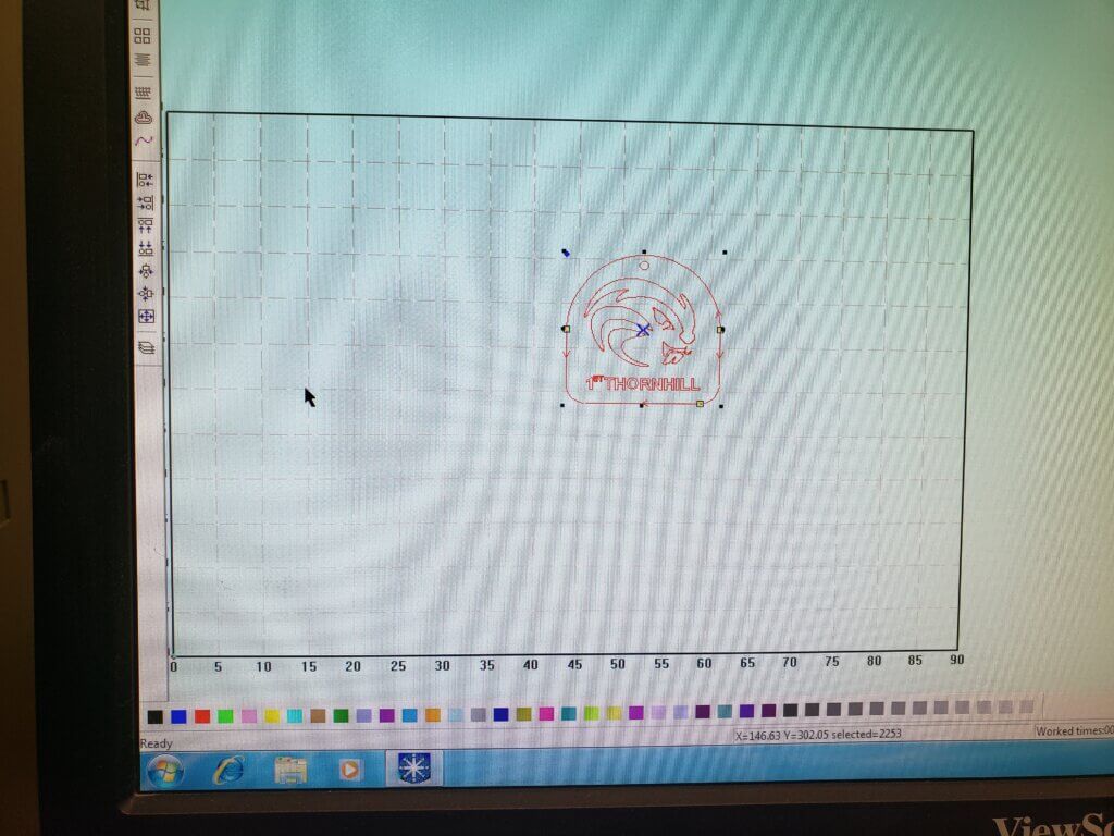
The full grid in the laser cutting software corresponds exactly to the cutting surface of your laser cutter – 90 cm wide by 60 cm high.
You need to ensure “Immediate” on the right side of the screen is no longer checked, or it won’t work.
Where your drawing is on the program’s grid is exactly where it will cut on the machine. Period.
To griddle or not to griddle?
The cutting surface of the machine is the entire surface when the griddle is not present.
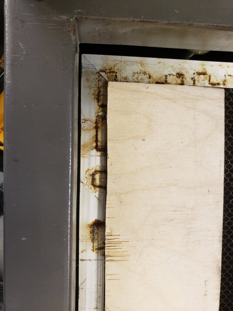
If you are using the griddle, your material is placed inside the border of the griddle, as in the image above. To cut up there, you need to move your drawing to the upper left corner of the grid on the screen… but not too close. You need to leave space for that griddle border.
Another option: test first, then place your material
If there is plenty of space for your material, load your design and run the Test first to locate the laser’s starting point. Then place your material based on the where the laser stopped.
Laser cutter Pause button is your friend
You started cutting, and something goes wrong – like a cut-out piece half falling in and half sticking out in a way that could interfere with laser head movement. Or someone needs your help. Or that bucket of cola from the burger joint wants out now and your job still has another 30 minutes.
Fear not. the Pause button will pause the cut. Take care of business, come back and resume.
Checking for errors
- Make sure original drawing is not red so you can see where the objects are
- Look for double little squares at the end of lines to identify crossed points and open shapes
- You might have to zoom WAY up to see them
- Tick only one box at a time to see errors by type
- Tiny artifacts can be spotted by looking for the little boxes
- You may be able to heal gaps by increasing gap fill size
- NEVER FREE-HAND LINE JOINS IN YOUR CAD. ALWAYS USE OSNAP.
TEST TEST TEST ON MATERIAL
We have found that material characteristics can vary from batch to batch, especially for MDF.
- Test a simple cut and engrave to see how it works on your material
- Adjust parameters as required
- Scale down your drawing and test on a smaller piece of material
Final notes
- Not sure about the thickness of the material? Don’t guess. We have a vernier caliper.
- Follow the instructions in our manual (always on the laser cutter) to make sure you don’t miss a step.
- BE NICE! DON’T HOG THE MACHINE!
- Break it into separate jobs. You might need to run it over several evenings.
- If it’s one big job – like a massive engrave – let the supervisor know first. They may want to leave early that night. Emailing before the evening is always a great idea. And maybe even let other members know that the machine will be tied up
- Instructables, Thingyverse and other sites have lots of projects. Google search is your friend.
